Tutorial – Morph-based Tank
Treads Using Relativity
Download the Example Files for This Tutorial
Here
With the release of Relativity 1.0, users were introduced
to the tank tread tutorial, where an individual link is cloned many times
in Layout and then moved around a pre-set path using Relativity’s Dr. Cycler
to control the motion. This is certainly one way to tackle the solution,
but can become unwieldy in scenes with many tanks, each with their own
set of links. An alternative method to having individual links is one that
uses morph targets to simulate the motion of a tank. Over the years, several
methods have been offered, including simple hand-keyed morphing, or morphs
controlled by LightWave’s cyclist. While these solutions seem to work on
the surface, or at least in limited situations, they each have inherent
disadvantages:
-
Scenes constructed using cyclist will react properly to changes
in forward speed of the tank, but not to rotation or reverse motion. Cyclist
also will not properly calculate motion blur sub-frame positions.
-
Scenes constructed using simple morphing will only support
forward motion at a constant speed--throw in changes to speed and direction,
and the solution breaks down. They also will not support motion blur
properly.
The Relativity solution has the advantage that it's fully
automatic -- tanks can move forward, backward, or spin around and the treads
will react appropriately, and they will properly motion blur.
This tutorial makes no assumption as to the user's familiarity
with the other methods, so we will start from the beginning of how to model
a tread with an appropriate morph map.
-
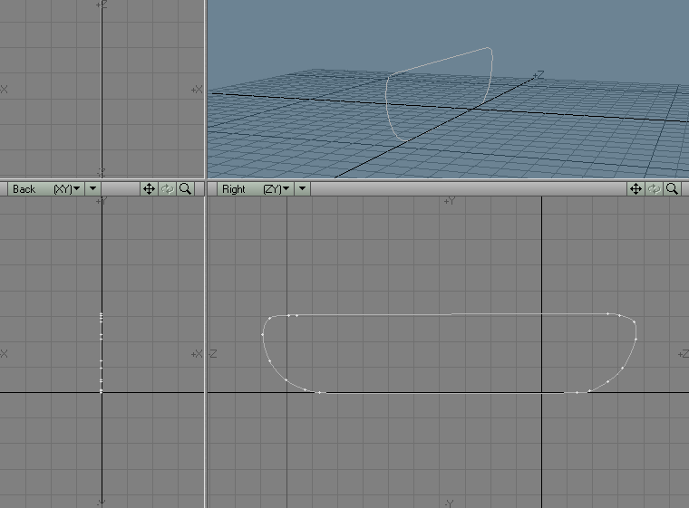
Start up Modeler and create a closed spline path that represents
the shape of your tread--be sure to draw it so that its "forward" end is
facing into the positive Z axis. Don't worry about evenly spacing your
points, but do worry about keeping the bottom part of the path straight,
as well as the top.
-
Locate the first point in your spline path, copy it, and
paste it to another layer.
-
In this new layer, select the point and press "p" to make
it a one-point polygon.
-
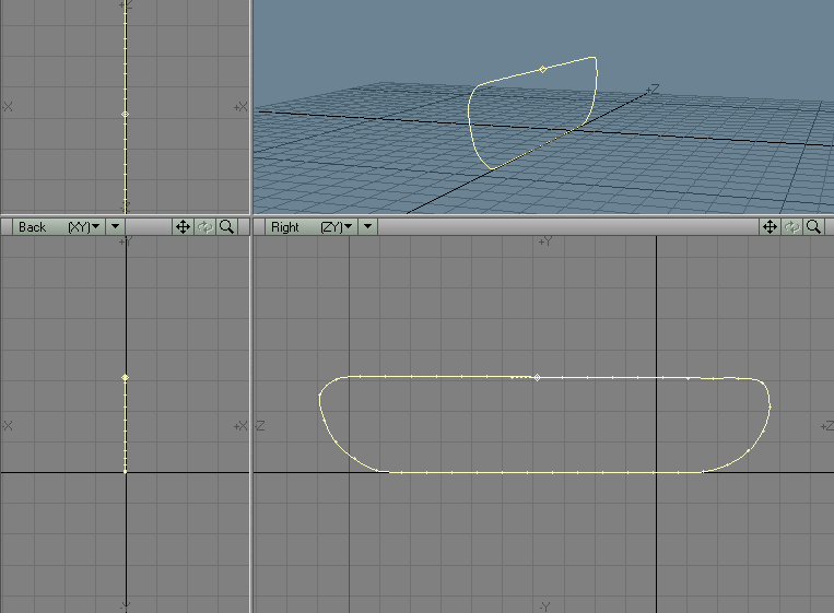
With the original spline in the background and the one-point
polygon in the foreground, perform a rail extrude. Be sure to set the Segments
to "Uniform Lengths" and give it a pretty good number of segments (values
of 40 or above seem to work well). You should now have a number of connected
two-point polygons with their points evenly spaced around the contour of
the original spline. Kill these polygons and select the naked points in
forward order (i.e. in the direction that the treads will be moving) around
the perimeter. I would strongly suggest making the start point somewhere
along the flat portion along the top (the reason for this will become apparent
later). With these points selected in-order, create a new closed spline.
-
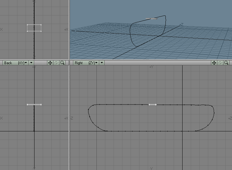
Using this spline, model a link object that is exactly as
long as the distance between two of the points…this is important, as we
want clones of this link to completely enclose the perimeter of this spline
when we're done. You can make your link as simple or complex as you like…for
this tutorial, I've created a very simple one.
-
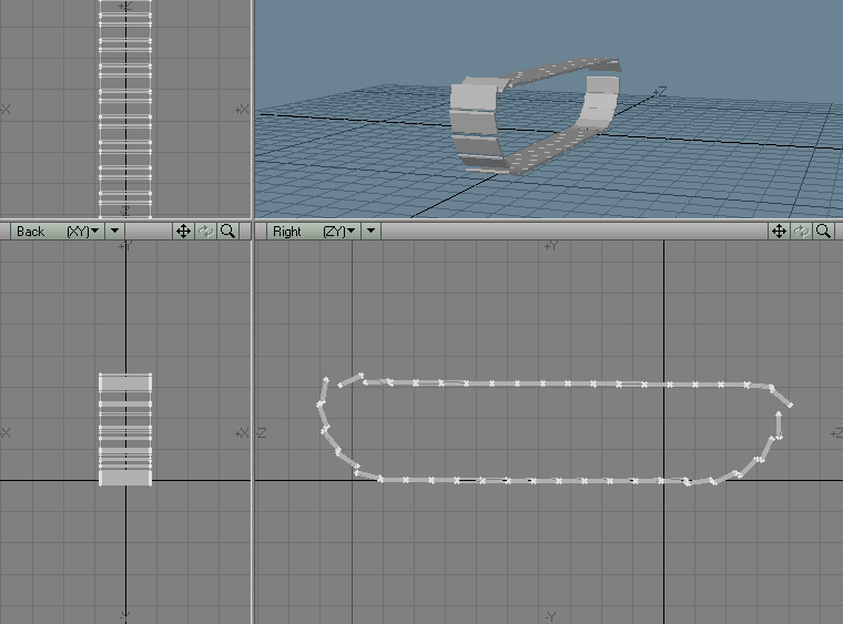
Position the link in the same spot as the first vertex in
the spline and do a rail clone (be sure to select the same number of clones
as the number of segments when you made your spline and select "Oriented").
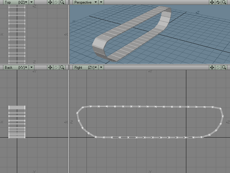
Your initial result is going to look just a little messy:
-
To clean this up, select each link element and rotate it
so that its tip touches its next neighbor. Here is the cleaned up rail
cloned tread:
-
The next few steps will be used to create the morph target.
Copy your current layer to another layer and switch to the new layer. Once
there, select all the polygons in the first link in the chain (it will
be in the same position as your initial link was).
-
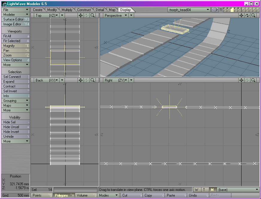
With the first link selected, delete it. Select the link
one step behind where the first link was and copy it. Now Do a Display->Hide
Selected to hide the selected polygons. Paste the copied link into your
object and select all polygons of the newly created link copy. Move this
link forward to where the first link was (and has now been deleted). Finally,
do a Display->Unhide All.
-
You have now created a morph target for your tread that represents
all the links rolling forward by the distance of one link. Go back to the
layer you were in prior to step 8 and make the morph target layer the background.
-
Apply the Map->Bkg to Morph operation and name the morph
map "tread2". Try switching back and forth between the base and tread2
endomorphs--if you have done it all correctly it should look like nothing's
happening…the tread object looks exactly the same. To verify that the actual
geometry is moving correctly in the morph, select points, groups of points,
polygons or groups of polygons and switch back and forth between the endomorphs
with these selected. You should then see that the geometry is indeed moving
forward by a link-length when the endomorph is applied.
-
Save your project so far and then delete everything but this
one layer and save to a new object--call it "morph_tread_final.lwo". Before
closing down modeler, use the measure tool to determine the exact length
of a link (be as precise as possible).
-
Start up Layout (you can also close down Modeler--we're done
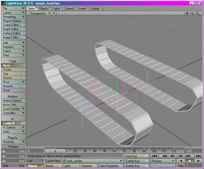
with the model), and load two clones of your "morph_tread_final.lwo" object.
Space them apart evenly and create a parent null for these…name it "Tank_Center".
NOTE:
be sure that you set up your "tank" so that it is facing into the positive
Z axis. Next, create a pair of nulls, called "track_null_left" and
"track_null_right", make these children of "tank_center" as well and move
them to the outside edge of the left and right tread objects, respectively.
When you're done, you should have "tank_center" as the parent of everything,
with the two morph_tread_final.lwo clones and the two track nulls in their
positions as if this were a real tank:
-
The next step will be the creation of an initial Relativity
morph expression just to see if we're in the ballpark. Apply the "Relativity_Morph"
plug-in to both the tread objects and open up the panel for the left tread
clone. Select "Dr. Morph-o" from the professors next to the morph slot.
In Dr. Morph-O, select the Target Object as ENDO:tread2, select the morph
type as "Replace" and select "tank_center" as the initial control object.
Your morph expression should look like:
&MORPH(ENDO:tread2,X(tank_center,t))
-
Replace the text "X(tank_center,t)" with just "t" (without
the quotes), so it looks like: &MORPH(ENDO:tread2,t)
-
Click Continue on the morph panel and play Layout's preview
between frames 0 and 30…if all was done correctly, you should see the link
object moving forward by one link-length over those frames.
-
Open up the Relativity_Morph panel again and change the expressions
to the following for the left tread object:
A: ODIST(track_null_left,t)/<tread length>
B: #a-floor(#a)
MORPH: &MORPH(ENDO:tread2,#b)
Substitute in the value that you measured for the link length
for "<tread length>"--for instance, I measured .409 for my tread length,
so this expression became " ODIST(track_null_left,t)/.409". Let's explain
some of the other pieces of this expression:
the A expression takes the oriented distance traveled by
"left_track_null" and divides that by the length of one link. Hence, every
time the left null moves forward by the amount equal to a link length,
the expression should roll over to 1.0, 2.0, 3.0, etc.
The B expression removes the part of the value in A prior
to the decimal point, so if A originally was 4.4329, B would become just
0.4329.
The value in B ends up acting just like a percentage in the
morph equation, so it can be substituted in without any further doctoring.
-
The final step in completing the setup is to copy the expression
from the left tread to the right tread, then changing "track_null_left"
in slot A to "track_null_right".
To test out your setup, keyframe the "tank_center" null moving
forward, backward, spinning around, etc. You should see the treads reacting
properly to any motion you can throw at it.
Copyright 2002, Prem Subrahmanyam, All Rights Reserved.
Return to the Relativity
Page.


