Chapter 1: the basic lamp assembly
1.1: The Basic Lamp Setup
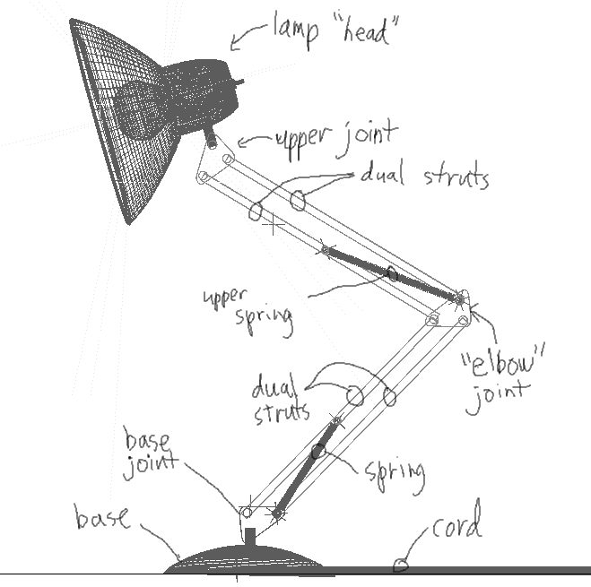
Figure 1 illustrates the basic assembly for the lamp.
Figure 1: Sketch of the lamp assembly.
Each "arm" of the lamp consists of dual struts, attached to the various joints, the base joint, the elbow joint, and the upper joint. There are also springs providing counter-tension running from the base and elbow joints to one of their respective connected struts. Finally, the head of the lamp is attached to the upper joint, and the whole assembly is attached to the base. The finished hierarchy looks something like this:
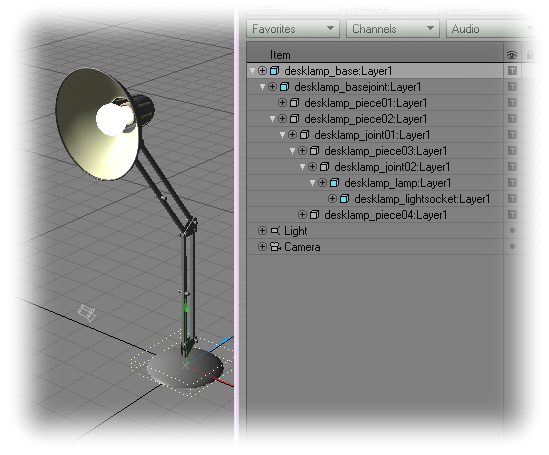
Figure 2: the lamp hierarchy.
Note that not even the springs are in place yet. First we need to focus on getting these basic parts functioning properly. Bring up the generic plug-in "Relativizer" and apply Relativity to "desklamp_piece01:layer1" and "desklamp_joint01:layer1". Now, a brief observation: if you move an actual desk lamp around, both the struts in each arm end up rotating at the same angle relative to the joint. So, if strut 2 is 30 degrees rotated, strut 1 will be also. Also notice how the lamp itself remains at the same angle relative to the world as you rotate any one arm of the lamp, so it would almost seem that the joint at the top of any two struts ends up canceling out the rotational values of the struts. This should give us enough of a description of the behavior of the lamp to apply some expressions to it. Rather than having to rotate both struts in an arm, it would make more sense to rotate one strut and have the other follow that rotation. Hence, we will automate the first strut "piece01" relative to piece02:
B(desklamp_piece02.lwo:layer1,t)
B: -B(desklamp_piece02.lwo:layer1,t)
1.2: Creating a Pseudo-IK controller for the lamp's head
At this point, you should be able to keyframe your lamp into any pose you want by simply keyframing the "piece02" and "piece03" struts of the lamp. Everything else should follow automagically. Were we just wanting to animate the lamp moving around a bit, this would probably be sufficient (except for setting up the springs, of course); however, since we want to create a Pixar-style hopping lamp, it would be easier if we had control of the position of the lamp's head at every point. Hence, we are going to set up a pseudo-IK type system where a "stretch" null will allow us to precisely place our head's height with respect to the base of the lamp.
Load the scene "desklamp_joints_final_pseudoIK_first.lws". This scene shows the lamp posed from a fully stretched to a fully squashed position (done by animating the bank rotation of strut 2 and 3) and a null keyframed to the position of the head at both extremes. Note that while the null matches up at the beginning and end, it doesn't match well for intermediate positions of the lamp. In the scene "desklamp_joints_final_pseudoIK_second.lws", the rotations of the struts in the lamp have been corrected to match the elevation of the null from the highest to the lowest position. You'll also see that there is a null placed near the base joint of the lamp, and another null, named "dist_null" with an Relativity GAP() expression applied to measure the distance between these two nulls. With this scene, we have captured what should happen with the stretch null moved to various heights…all we need to do now is build an expression that plays back this animation based on the distance between the two nulls--the base null and the stretch null…basically a link between keyframed values and the positions of these nulls.
To achieve this linked playback of the animation, we're going to use Dr. Blend Machinist on the animations of struts 2 and 3.
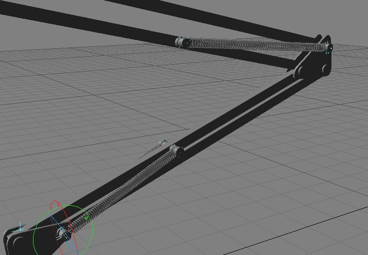
1.3: Springs and things
Next, we will turn our attention to the springs. Load the scene "desklamp_with_springs_first.lws". You may also want to examine the spring object, "lamp_spring_final.lwo" in Modeler to see how it was designed. It has two endomorphs, the base and the "compressed" morph…the compressed one is significantly shorter than the base. While in modeler, the distance between the centers of the spring ends in the normal and compressed modes was measured. These turned out to be, respectively, 2.095 m and 1.530 m. Here are some things to note in the spring scene itself:
Finally, we need to assign a morph expression to each of the springs:TARGET(spring_tip (#ex),t)The (#ex) will cause each to point to its appropriately numbered tip null, "spring_align (1)" will point to "spring_tip (1)", "spring_align (2)" will point to "spring_tip (2)", etc.
- Variables Panel:
- A: BLEND(0,2.095,1,1.530,GAP(spring_base (#ex),t,spring_tip (#ex),t))
- Main Panel:
- MORPH: &MORPH(ENDO:compressed,#a)
What this will do is create a blend value from 0 to 1 as the expression "GAP(spring_base (#ex),t,spring_tip (#ex),t)" changes values from 2.095 to 1.530 (again the "#ex" in the expressions will help each expression point to the appropriately numbered base and tip nulls). When the distance between the two nulls is 2.095, the BLEND expression will evaluate to 0, which will mean that the spring is 100% base endomorph. When teh distance is 1.530, the BLEND expression will evaluate to 1, which will make the spring 100% morphed to the endomorph "compressed".The scene file "desklamp_with_springs_final.lws" shows the lamp with all the spring expressions in place.
Chapter 2: The Cord
We will now turn our attention to animating the lamp's
cord, a critical part of the original Luxo, Jr. animation. Ideally,
we want to be able to drag the lamp around and have it automatically generate
impulse waves down the length of the cord, as well as follow the lamp without
having to resort to any great amount of manual keyframing.
Open up the scene "cord_first.lws" and take a look around. Not much
to see...just a subdivided cord object and a blank scene. The first
step toward getting a proper cord is setting up a Relativity bone snake.
Invoke the generic plug-in "*REL:Scene_Professors". It will bring
up an interface where you can choose one of several scene professors from
the drop-down list. Choose Dr. Snake-maker and use the following values
in the panel's fields:
- Let's set up bones for this object: cord.lwo
- How many bones do you want: 30
- How long is your object: 28 NOTE: this is in meters
- Everything else left at its default value.
Click OK and drag your scene slider forward/backward
(or use the left and right arrow keys) to reset everything. You should
see a jumble of bones around the end of the cord object...don't panic; this
is normal. Relativity, by default, will leave all these bones inactive...in
order to get them in their proper position, we're going to need to rest
them with Relativity disabled:
In order to stretch out the bone snake, keyframe the object "cord_parent" to Z= -29 by frame 10. You might want to experiment around with keyframing the cord parent to various positions in space and watch how the bones snake around behind it. The scene "cord_second.lws" shows the expected results of all the previous steps.
- Invoke the generic plug-in "*REL:Disable_Relativity". You should see a pop-up appear indicating that Rel is now disabled
- Move the frame slider back/forth by one frame. All the bones should now be extended down the length of the cord
- Select the first bone, press the "r" key to rest it, down-arrow to the next bone, and repeat until all bones are rested
- Invoked the generic plug-in "*REL:Enable_Relativity" and cycle the frame back/forth once again...your object should now be jumbled with the bones.
While it may seem odd for now, the reason for splitting the motion of the head of the cord into two motions will become apparent in a few minutes...suffice it to say for now that it is purposeful that "cord_parent" move only along the XZ plane (i.e. the "floor") while "cord" moves only along Y. The example scene "cord_third.lws" shows these steps completed.
- Duplicate the keyframe for "cord_parent" on frame 10 to frame 9 (i.e. go to frame 10 with "cord_parent" selected, press Enter once, change the frame value to 9 and press Enter again) and set all channels on frame 10 to linear in the graph editor.
- Keyframe "cord_parent" to XYZ=<2.4411 m, 0, -31.3896 m> at frame 22.
- Kill the keyframe for "cord" at frame 0.
- Keyframe "cord" to XYZ=<0,0,0> at frame 10 and frame 22
- At frame 16, keyframe "cord" to XYZ=<0,1.0604 m,0>
- Note that the cord now takes a small "hop" from frame 10 to frame 22
Click the Copy button and paste these expressions to the other 29 target nulls (HINT: you can select target object 29, press the escape key to remove focus from any of the fields, press the "v" key to paste, press the down arrow key to go to the next object, press "v" again, etc. until you have pasted the new expressions to all of the nulls). Following is an explanation of how these expressions work:
0.933333*(0+1) = 0.933333 * 1 = 0.93333
This expression for snaktrg1 would evaluate to 0.93333*2 = 1.866666, for snaktrg2 it would evaluate to 2.799999, etc. Interpreting this, each null follows at a multiple of 0.93333 behind the "cord_parent" null object in X and Z.
Variables panelThis will subtract a damping factor from the Y expression for the target null...this factor will get increasingly larger the further down the chain we go...but the COND() statement in variable slot B will prevent the damping value from ever becoming negative. This expression uses the X of "damp" to control the damping amount...try keyframing "damp" to various X values and see how the cord reacts.
Main panel
- #ex*X(damp,t)
- COND(#a<1,#a,1)
- Y(cord.lwo,t-#ex*0.1)*(1-#b)
Variables Panel:The example scene "cord_fifth.lws" shows all this in place. Try keyframing "damp" and "delay" to different values to see how the cord target null expressions react.
Main Panel:
- #ex*X(damp,t)
- COND(#a<1,#a,1)
- XMINPATH(cord_parent,0.933333*(#ex+1),t)
- Y(cord.lwo,t-#ex*X(delay,t))*(1-#b)
- ZMINPATH(cord_parent,0.933333*(#ex+1),t)
Chapter 3: combining it all together
The scene file "desklamp_with_cord_and_springs.lws"
shows everything combined. The lamp is hopping around (using the stretch
null to control the position of the "head") and the cord is automatically
dragging and pulsating behind. If you examine the expressions, you
will see that things have been modified a bit further from what you've created
in previous sections of this tutorial. These changes are further explained
below.
3.1: Adding some Expressions Finesse
Once I started animating the lamp, it
became clear that the stretching motion provided by the stretch null was
not enough to give the lamp some follow-through and recoil from each of its
hops. Further, it seemed that it needed to lean forward a bit more
as it took off to give it a sense of carrying itself forward into each leap.
To facilitate this need for extra control, I created two nulls, "upper_rotate"
and "lower_rotate", that I could use, with modified expressions, to add extra
rotation to the upper and lower arms respectively. The bank expressions,
then, for piece02 and piece03 were modified to:
B(SELF,#a)+B(lower_rotate,t)
and
B(SELF,#a)+B(upper_rotate,t)
respectively. This will add the bank value of the appropriate null to each arm, allowing finer control of their motions. You can examine the keyframed bank values for each of these nulls to see how they were used to better animate the lamp.
Once the hopping motion had improved, it became apparent that the lamp's head was not showing any of the necessary inertia relative to the lamp's upper arm. If the lamp were extending itself rapidly, the head should swing slightly downward, where if it's contracting, the head should swing slightly upward. The following expressions on the lamp's head took its world-coordinate speed and direction into account to add some extra rotation:
and for the actual bank expression,
just use F:
If you examine the scene, you will notice that this expression adds just a little wobble to the lamp's head as it bounces around. One exercise for the reader...it might be better if the lamp head had a slight delay in reacting to its motion....what changes could be done to A and B to give the lamp a several-frame delay?
Finally, a modified "flashlight" expression is used to ramp up the lensflare intensity based on the angle of the light to the camera:
Channel expression: (0.7*#r*#r*#r) //cube the value to make it "spike" more narrowly
Conclusion
This animation should help you understand just how useful expressions can
be in your work. Imagine having to animate all those struts, springs,
joints, and lensflares by hand (and imagine, most of all, having to go back
and tweak some motion just slightly and needing to re-do all those keyframes
and envelopes). Using Relativity expressions, animators have a world
of tools available at their fingertips to take their animations further...all
the way back to the venerable Luxo, Jr.
All files Copyright © 2002, Prem Subrahmanyam, All Rights Reserved. Object, Scene, and Animation files may be used for personal education, but may not be redistributed in any form without the express permission of the author, Prem Subrahmanyam.